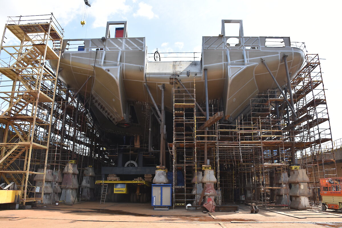

The hull of Australia’s new Antarctic icebreaker RSV Nuyina is rapidly taking shape. Some of the key components of the ship are currently being welded and fitted as the hull (the base of the ship) nears completion. Once the hull is complete, the dry dock will be filled with water to allow the ship to be floated out to a larger wet dock, where construction of the superstructure (upper part of the ship) will begin.
The images show:
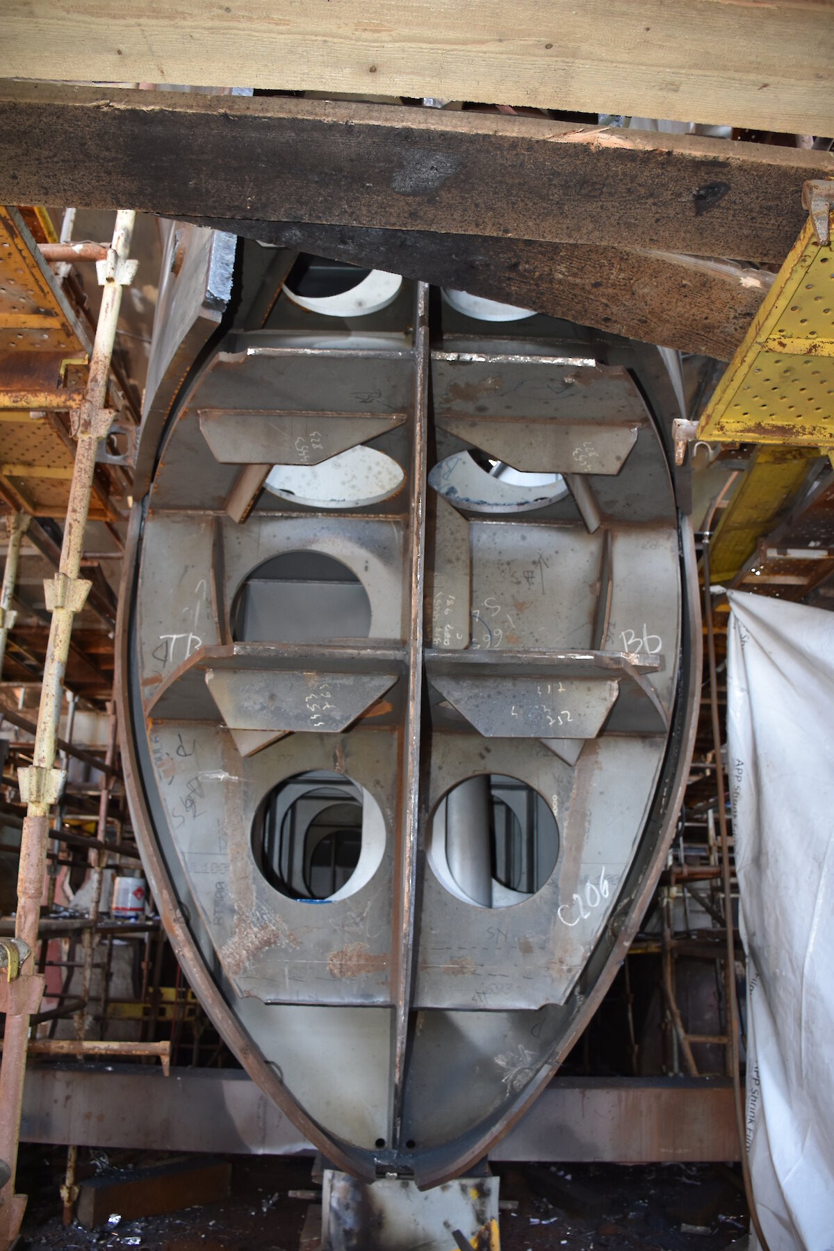
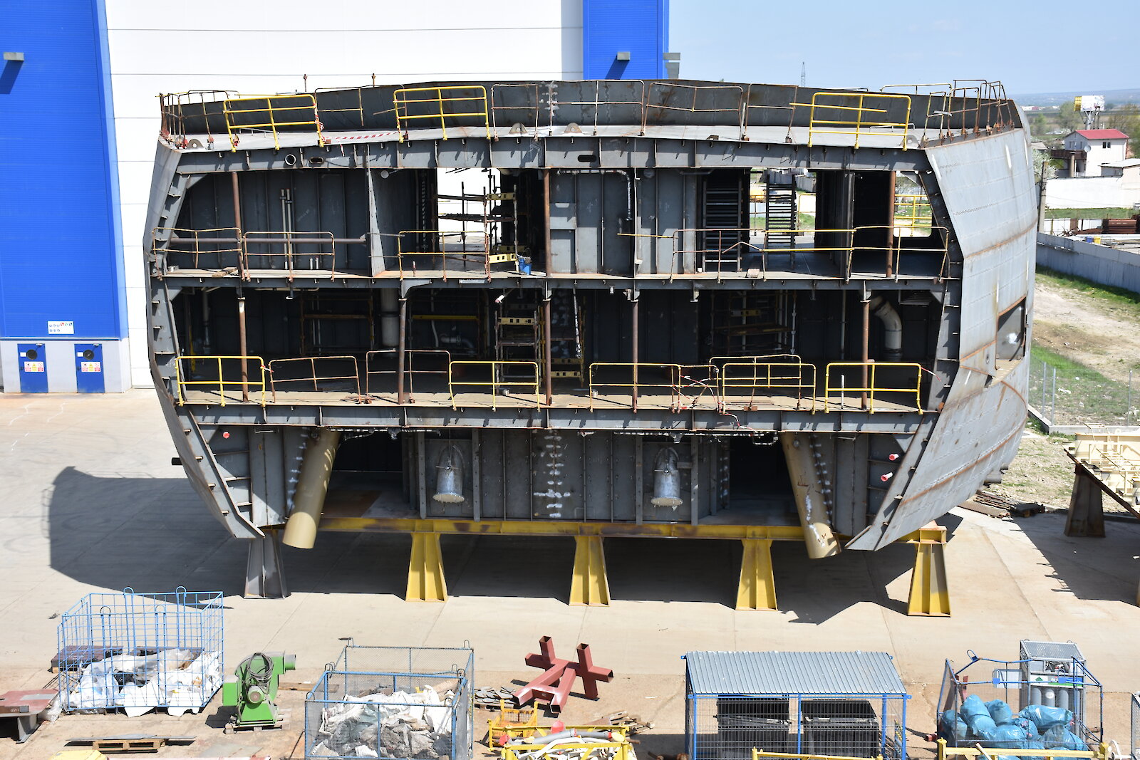
- This 300 tonne section is part of the top of the hull. At the bottom of the section are two tubes, called ‘hawse pipes’, through which the 275 metre-long anchor chains run when deployed. When not deployed, the chains are stored in ‘chain lockers’ behind the bell-shaped ‘end connectors’ that are visible between the hawse pipes. These end connectors connect the ‘bitter end’ of the anchor chain (the last link in the chain) to the ship. The bitter end link is attached to a quick release in the event of an emergency, allowing the chain and anchor to be cast from the ship. The deck above (deck 5) is the mooring deck for winches and ropes to tie the ship up in port. The deck above that contains an air chemistry lab, cargo space for dangerous goods, as well as a paint store and carpentry store.
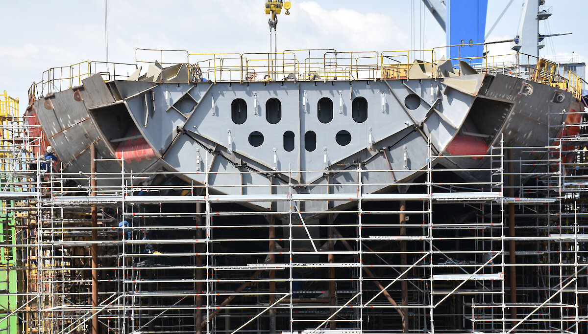
- The bow of the ship with ‘anchor pockets’ (recesses to house the anchors) visible on each side of the ship. The anchors will sit flush against the pockets to help streamline the hull form.
- One of the ship’s two 8 tonne anchors, with its length of chain (275m) behind.
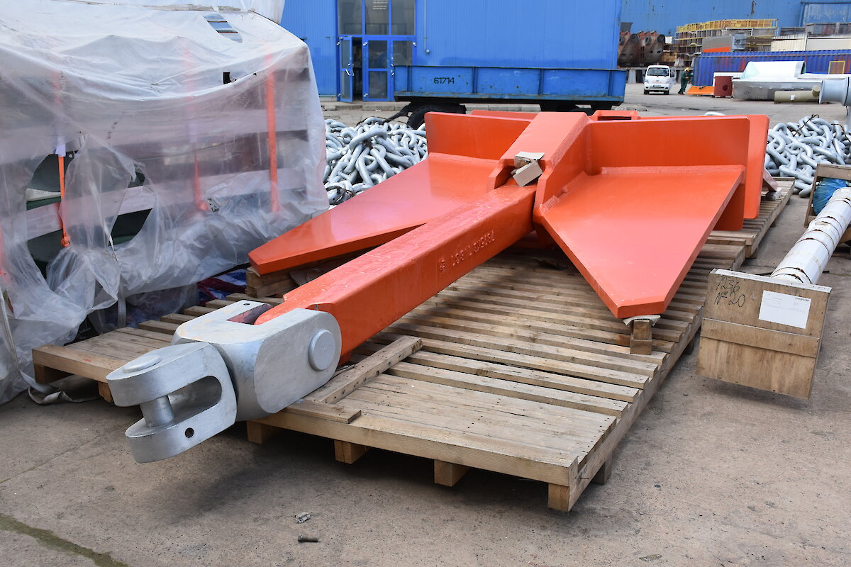
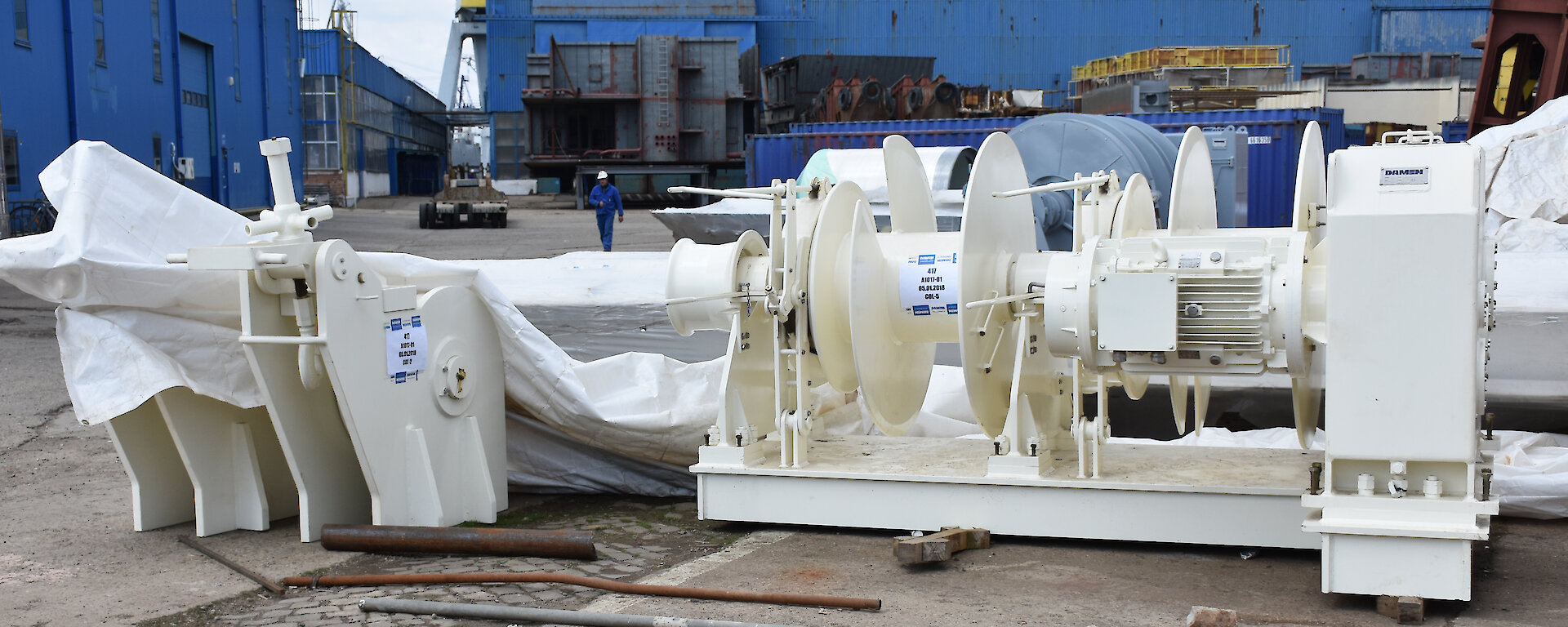
- This mooring winch or ‘windlass’ (on the right) will be fitted on the mooring deck to winch ropes used to tie up the ship while in port. To the left is a ‘chain stopper’ which secures the anchor and chain when not in use.
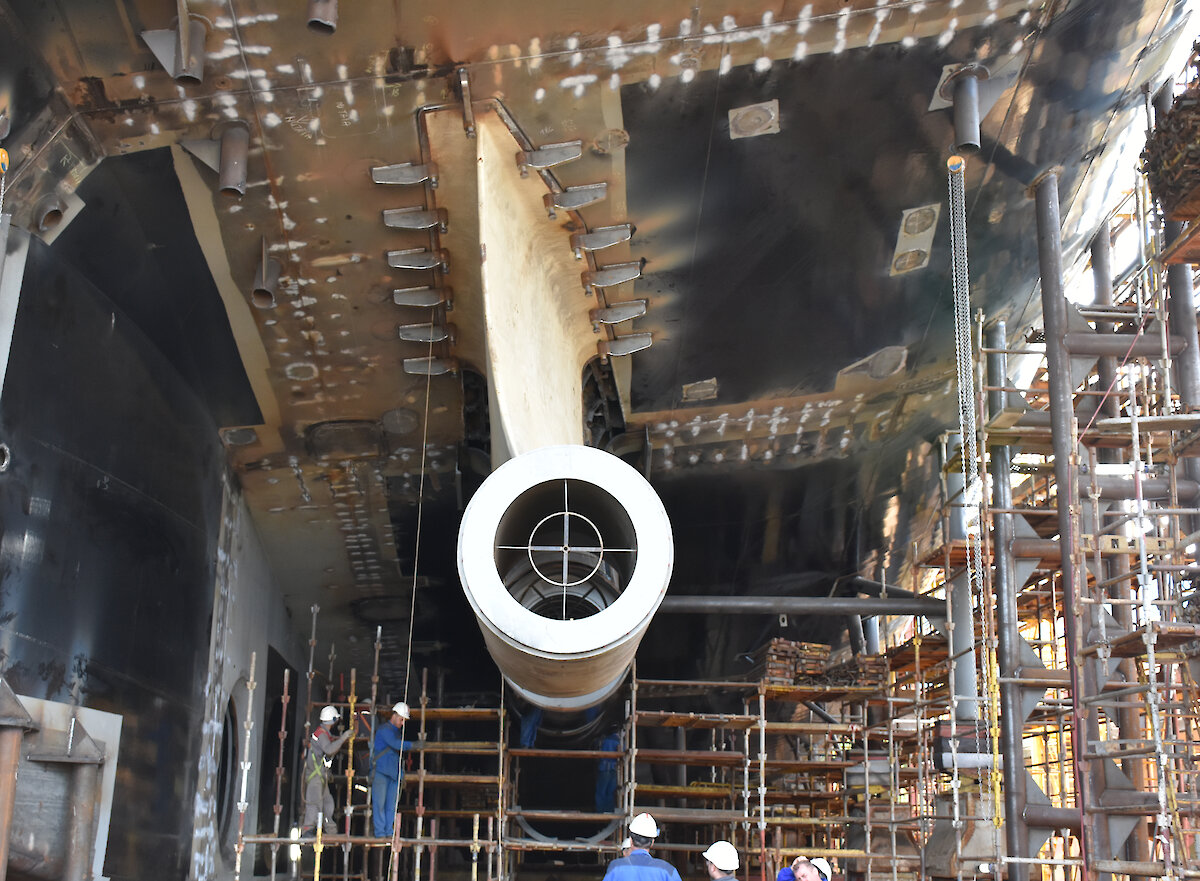
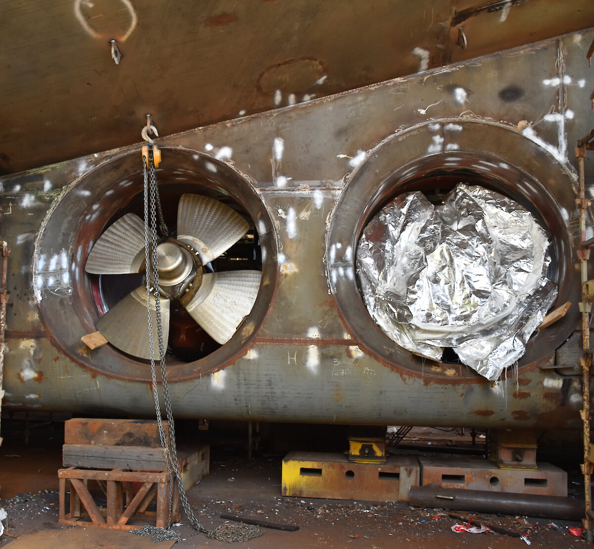
- This is one of two ‘gondolas’ that will hold the ship’s propeller shafts. Each one is made of 80 tonnes of steel. The length of steel above the propeller shaft tunnel will help deflect sea ice broken up by ice knives at the rear of the ship (see next photo). The cross at the front of the tunnel is for a laser sighting to ensure the gondola is correctly aligned with the ship’s engine. The complex and precise nature of the gondola requires a specialist team of 27 welders to install it. The gondola must be preheated to 150°C before welding can commence, as welding cold steel could cause it to expand and contract unevenly, affecting alignment and possibly causing the steel to fracture. The welders will each spend one hour on the job before another takes over and will have to wear wooden-soled shoes to cope with the heat. Once the welding is complete the gondola will need to be cooled slowly, to prevent warping.
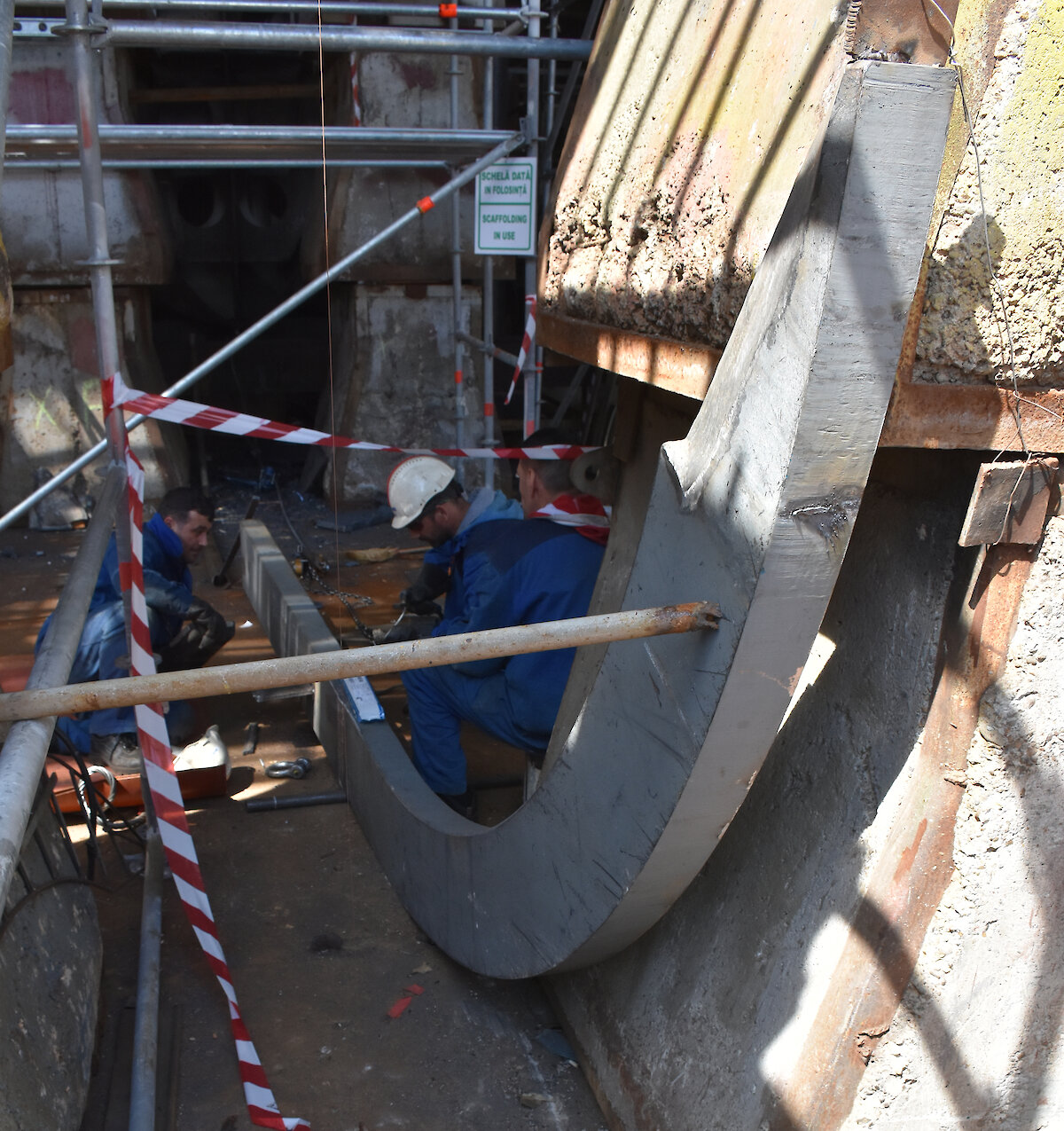
- At the stern of the vessel are two ice knives that are integrated into the rudders and ‘gondolas’ (see previous photo) to help protect the propellers and propeller shafts from ice when the ship is moving backwards. A gondola is being installed beneath the left ice knife, using a flat-bed truck and a frame, to lift and hold it in place.
- The two rudders that will be installed beneath each ice knife. Hatches in the rudders allow ingress for maintenance. Each rudder weighs 33.5 tonnes. The shaft around which the rudder turns, called the ‘rudder stock’ weighs 31.2 tonnes and the nut that secures the rudder to the rudder stock weighs 1.5 tonnes and has a diameter of 1 metre.
- This steel shape forms part of the ship’s ice knife at the bow. The ice knife will help to split and distribute ice under the vessel after it has been broken up by the weight of the bow.
- This J-shaped piece of 100mm thick steel will be welded on to the central spine of the ship’s ice knife on the bow (see previous picture).
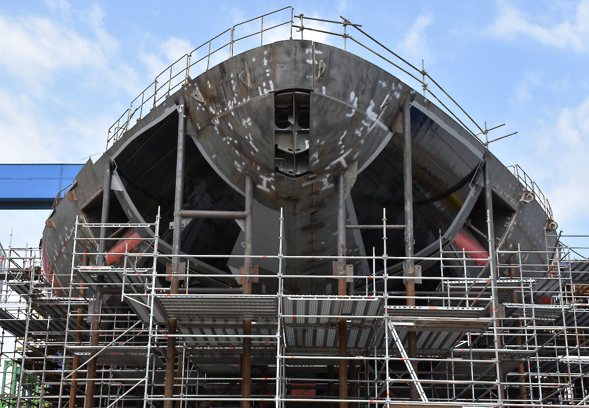
- The bow of the ship where it first contacts the ice. Once complete, the struts (below) and lifting lugs (at top) will be removed and the steel resurfaced in preparation for painting.
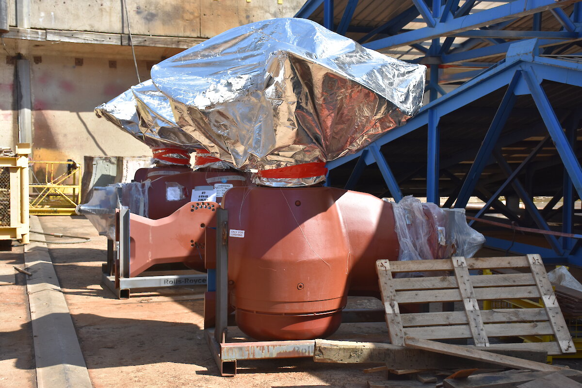
- These tunnel thrusters allow the ship to spin on a dime and hold a set position (‘dynamic positioning’) within ±20m accuracy. There are 6 tunnel thrusters — three at the front and three at the rear — each requiring 1,300kW of electrical power for maximum thrust. Among other uses, they will hold the ship in place during deployment of scientific equipment in a range of sea states, as well as during small boat deployment and cargo operations.
- Two of the tunnel thrusters being installed.
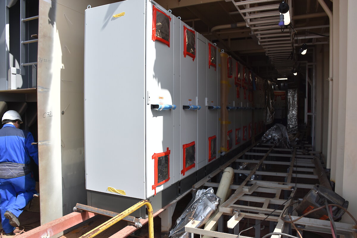
- This photo shows the beginnings of the switchboard room on the aft port side. The switchboard will take power from the electrical generators and redirect it where it needs to go, to run all the electrical components on the ship, including computers, lights and laboratory equipment.